Creating my first PCB — Object
But before we get to that… let’s talk processing. I’ve been using the Arduino as the brains for my projects for a while now. It’s gotten a bit…boring (not really, but it is time to move on!) What’s the next natural step after spending over a month tinkering with an Arduino? More microcontrollers!

Introducing the ATTiny85! A beast of a tiny chip that features an 8-bit programming platform, with 8kb of flash memory, 512 bytes of EEPROM, 512 bytes (again) of SRAM, and complete with 6 GPIO lanes, ADC’s, and a smorgasboard of other misc. features like an internal clock- which will be important. Fortunately, the spec limitations were not as important.
So here comes the task- design a printed circuit board (PCB) using this tiny microcontroller as the brains. The goal? To create something “interactive”.
With such a vague prompt, the first step was to brainstorm. I partnered up with Torshawna Chew and Ethan Wang on this project. Here are some of our ideas-


We ended up going with the MedPuck as it seemed both the simplest and most impactful idea. Plus, it worked well with the technical requirements to implement a NeoPixel LED strip into our project.

To put it simply, the MedPuck is a weight activated medicine timer that uses an LED strip to provide feedback on when a medicine should be taken. It is designed to be dead simple and frustration free. The only controls are a spinning ring used to set the timer between common intervals of 4/6/8/12/24hrs (in the demo case, we switch this to seconds), and a platform that activates a button when a pill bottle is placed. The button starts the timer, and LEDs light up when its time to take pills. This is aimed to be accessible and useful in keeping a consistent medication schedule.


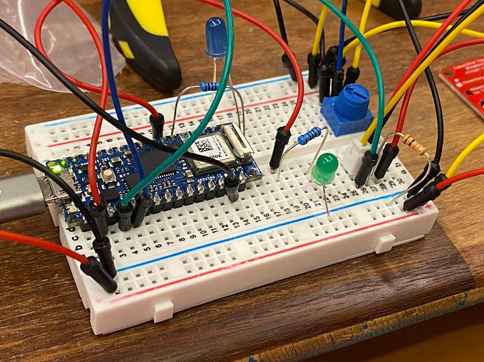
We started off by building a test circuit trying to control the NeoPixel strip with the ATTiny85. You’ll see in the photos that the (pesky) Arduino Nano 33 IoT is still around. That’s because its actually a pretty convenient 3.3v power supply, which the ATTiny85 also runs on. In the final product, power will be supplied by a coin cell battery.


We added a trim pot to the prototype- this would be integrated with a gear-based enclosure and a belt (made from a rubber band) to allow the turning of the side to control the timing of the circuit. Watch the video below of us progressing through our electrical prototypes.
In this video you see three different stages of the prototype and code. The first stage is just a simple test that lights the LEDs on the button input. The second stage uses a timer to light up the LEDs in sequence after the bottle is placed down. We use a bottle of ModPodge as the button requires a relatively high activation force. This will be reduced by adding weights to the platform in the final enclosure, thereby increasing the sensitivity of the button and allowing for lightweight pill bottles to be used. Finally, the third stage shows the settings option by spinning the trim pot. The lights change to a blueish white color and reflect the time (1 LED- 4 hours/seconds, 2 LED 6 hours/seconds, etc.). After no more input is detected, the lights flash to allow the user a grace period to make any final changes. Once the confirmation period is over, the timer starts with the new values.
One note is that this new timer value should be stored in the EEPROM — however, I was unable to get this implementation to work. For some reason either the EEPROM was not being written too or it wasn’t being read from properly. I didn’t have time to diagnose and debug this (for now) — which would have been a massive PITA on a chip without a serial output.
I did mention an enclosure right? The video shows some sneak peeks at my enclosure design. This is actually for a separate project for my Form class- as it wasn’t a requirement for this Object lab. I created the enclosure in Fusion 360 and you can see the initial version and a (near) final version animated in this video.
The design was made to be as simple and sleek as possible. It was also split up with ease of assembly in mind — specifically, these parts are to be 3D printed and assembled by fitting them together. Theoretically, no glue or screws are required, and gravity and friction will hold everything together. This allows for easy replacement of the coin cell battery, which brings us to the design of the printed circuit board.

The PCB design was relatively straightforward. After updating the electronic schematic (below), we initially used both layers to route the traces. However, this ended up being a little too complex and unreadable for our liking, so we played around with positioning the various components and got the result on the right, which required only a single layer and looked much better both in terms of readability and in terms of aesthetics.
Attached below are the final versions of the code, schematic, and PCB design, as well as a confirmation of our order, which by this time is almost here! Exciting!
Thanks again for reading! If you want to build the MedPuck yourself, I’ll be making another post once the final enclosure and assembly is built. Next, we’ll be using more analog inputs for another fun project. Thanks for your time, and as always see you next time!