Logic Probe Build Log
This year I’m taking some cool courses as part of my Creative Technology & Design major at CU Boulder. One of these classes is ATLS 3300 — Object. Object is a class where we learn and use microcontrollers and basic electronics, to build really cool things. Our first matter of business this semester is to build a logic probe device, that will help us debug HIGH/LOW signals from our microcontrollers.
We followed the following instructions from a TA in the course.

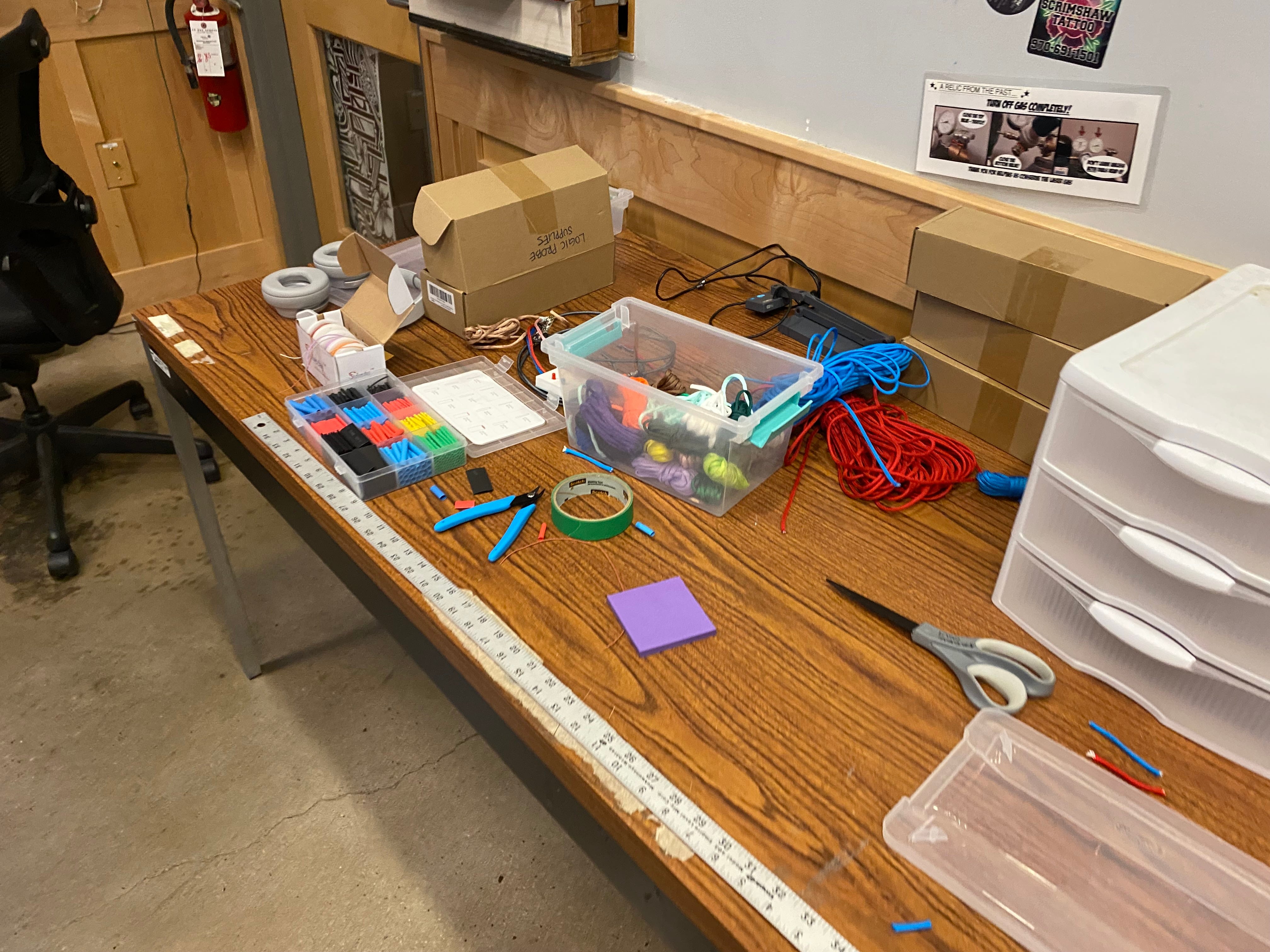

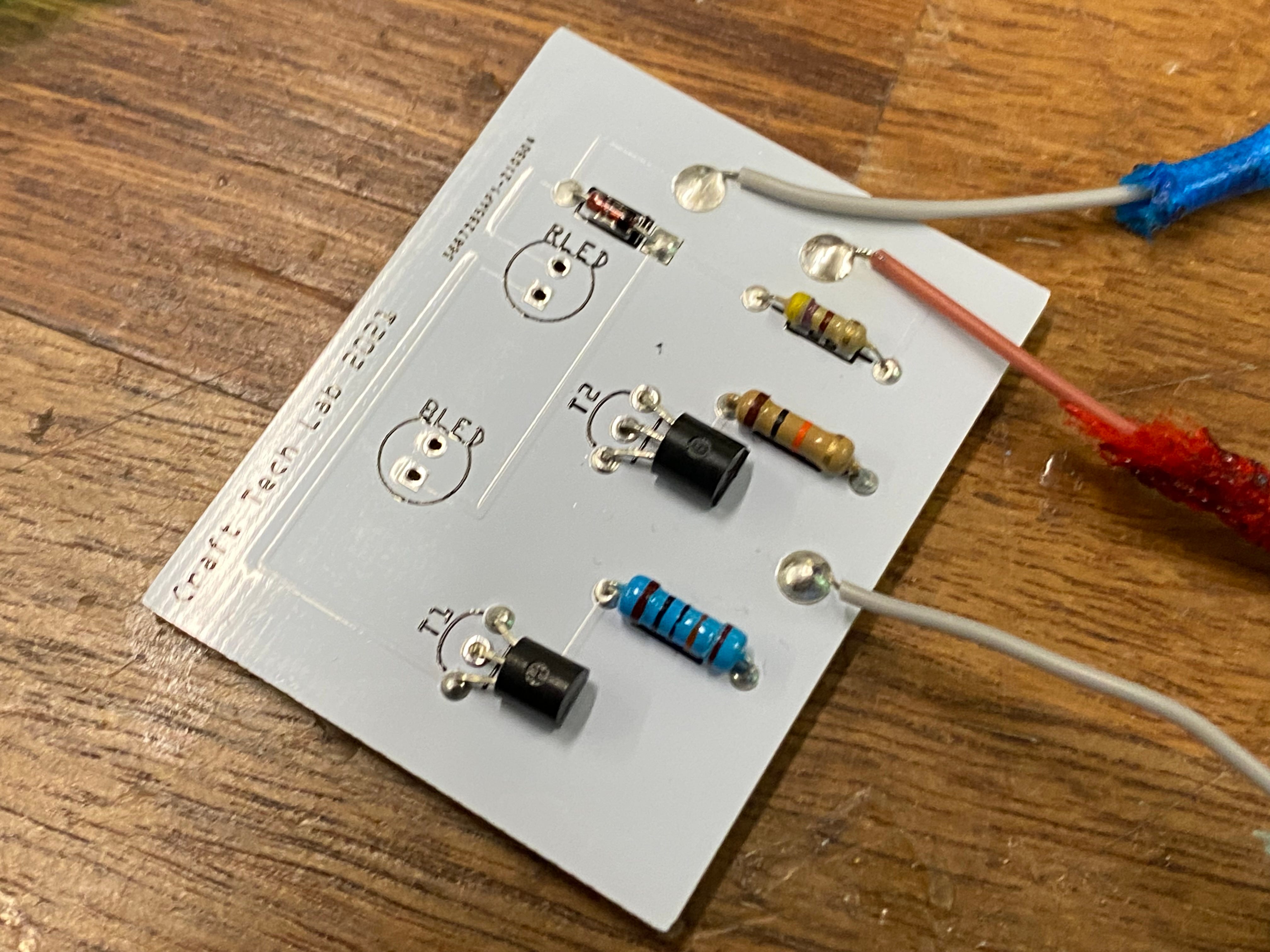
After receiving instructions from our TA Chris Hill, we set off with the provided PCBs and fitted the components (also provided). This was relatively simple to do, and there’s not much of note here, except that the LEDs where removed as they are installed after the enclosure is built.

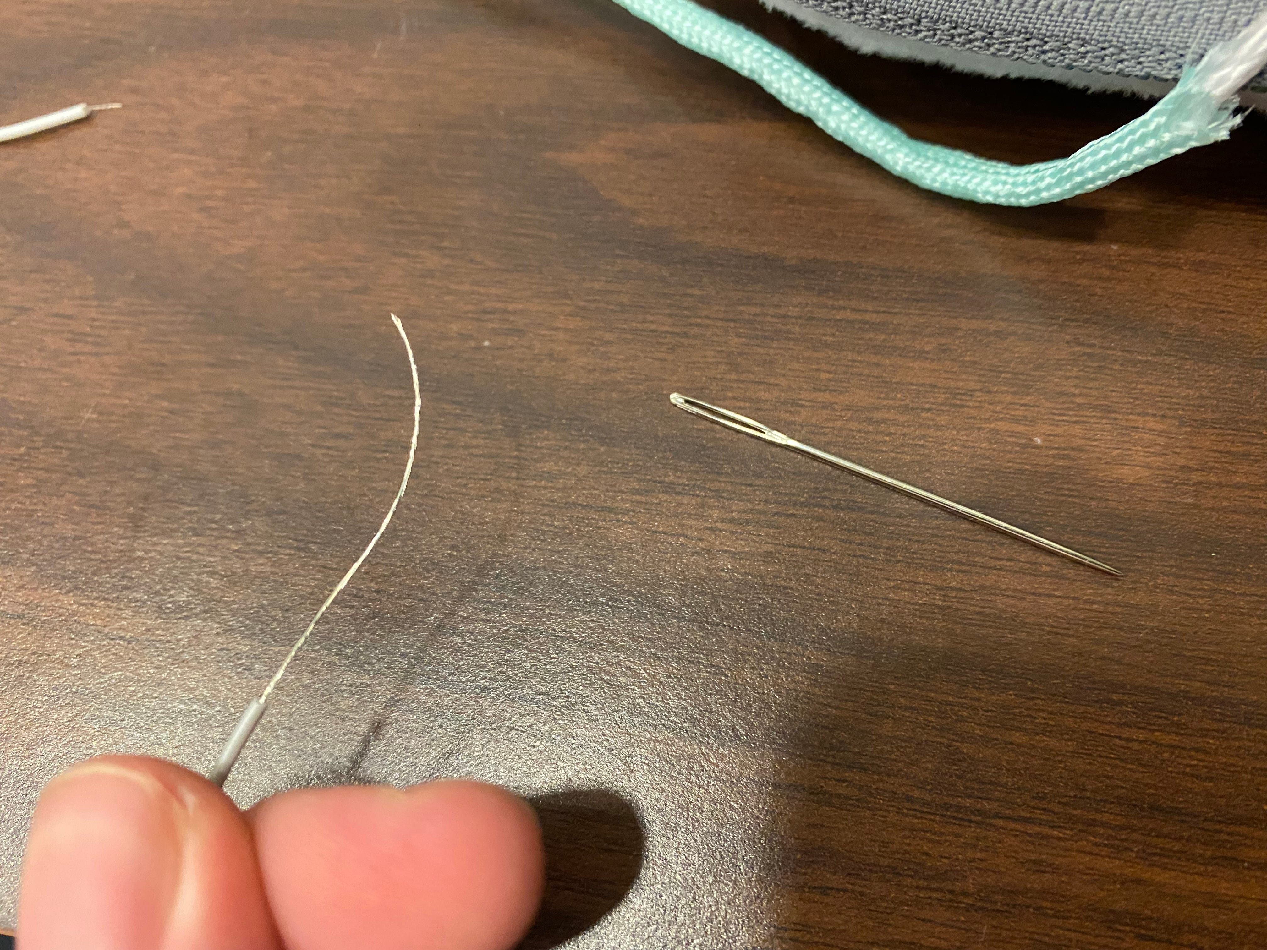
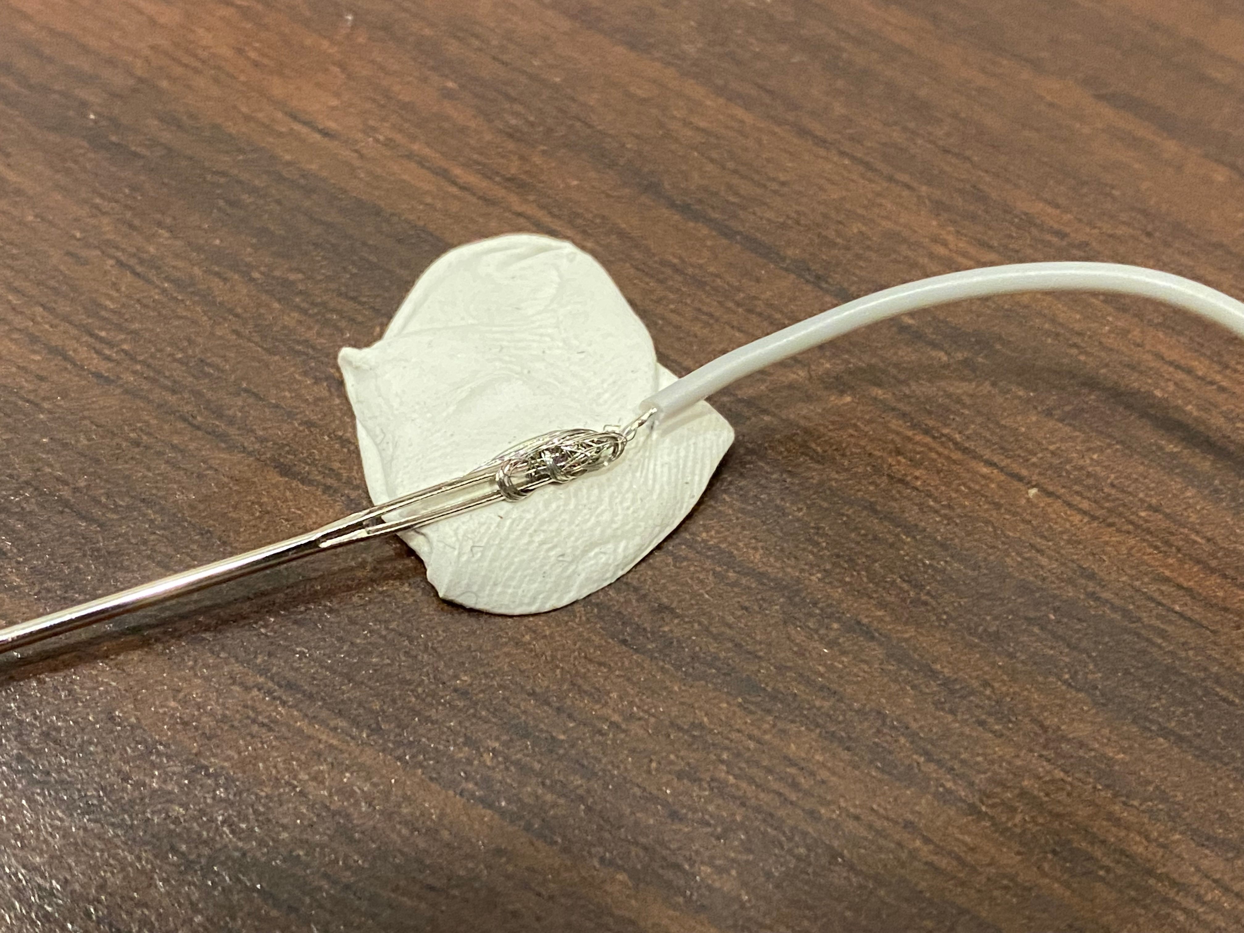
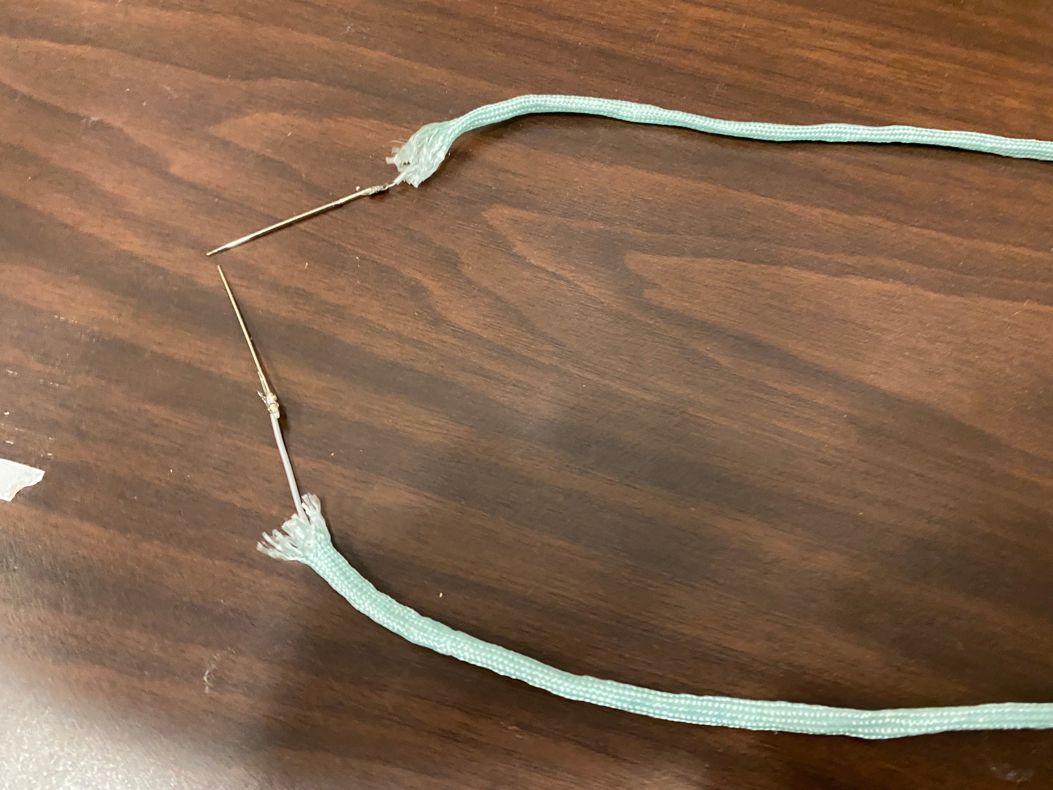

Next up on my plate was to create the probe wires. These are what will be used to test for HIGH/LOW states on the microcontroller. If I haven’t mentioned it already, I’ve been working on this project with my lab partner Ethan. While Ethan got to work soldering the connections on the PCB, I went out to cut and build the probe wires. We chose a nice shade of mint for our paracord, and I soldered two thin wires to sewing needles (our probe). The fairly challenging part was then threading the wire and needle through about a foot’s length of paracord. Once that was done however, two pieces of heat shrink finished the build.
As I mentioned, while I worked on the probes, Ethan was soldering our first PCB. I say first, because it was at this point I decided to make my own as well. Mainly to improve on my soldering skills, but also I felt that this would be a useful tool in future projects. The soldering went well, and I tried to take my time to create a nice looking circuit board.
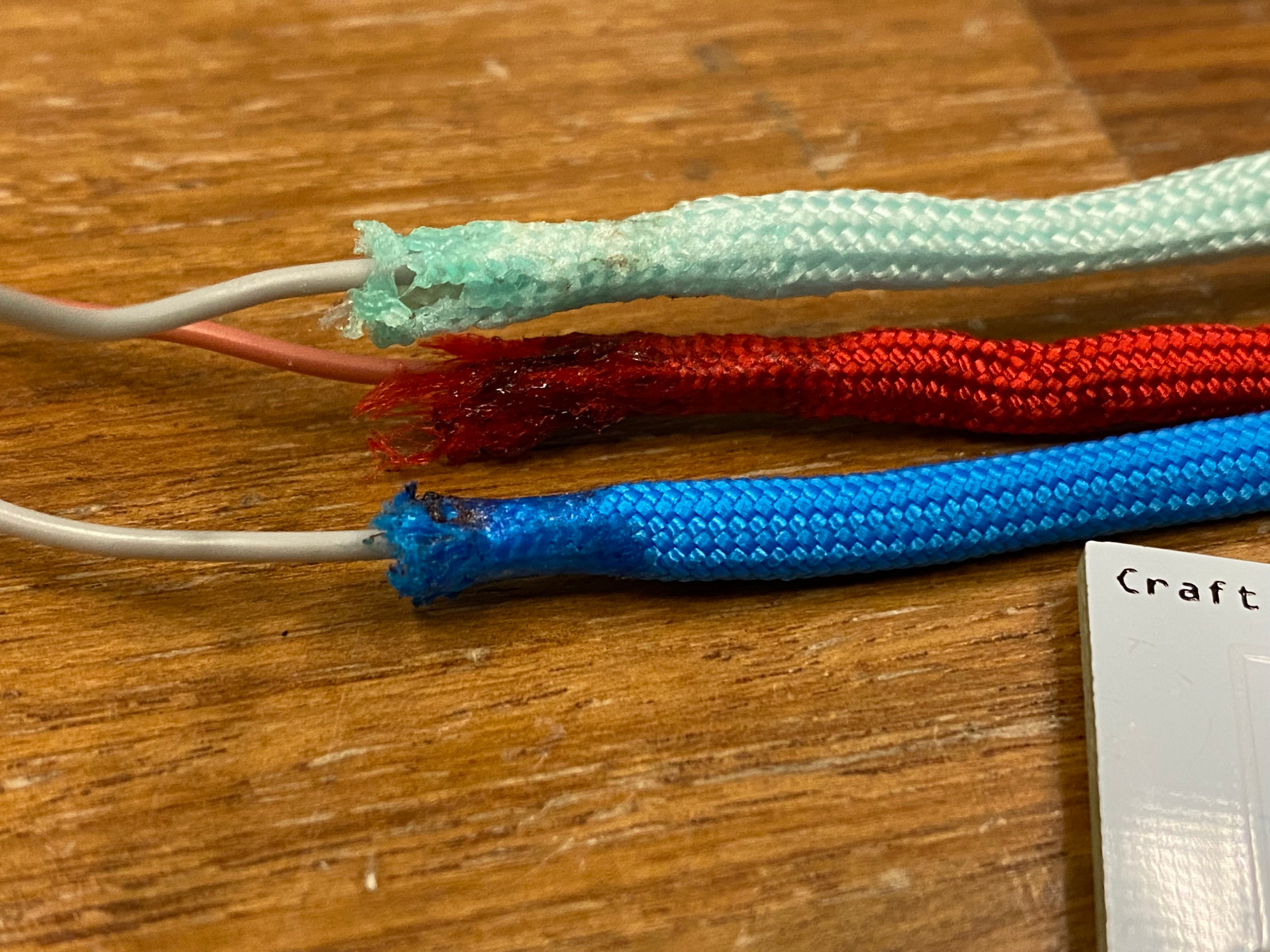
To finish the day, I fabricated the power and ground wires. Twice the Logic Probes means 4 total wires to create. The technique here was similar to the probe wire, except that alligator clips and crimping were used instead of needles and soldering. I wrapped the exposed wire around the alligator clip, crimped it tight with some pliers, and used some heat shrink once again to finish it off. I messed up a little bit on the first red wire by using too much heat shrink and letting the paracord get away, and you can see this in the third photo. Fortunately, there’s no drawback other than looking a little wonky.
And with that done, part 1 is complete! Next steps include 3D printing the enclosure, soldering the LEDs, and final assembly and testing. We’re almost there!
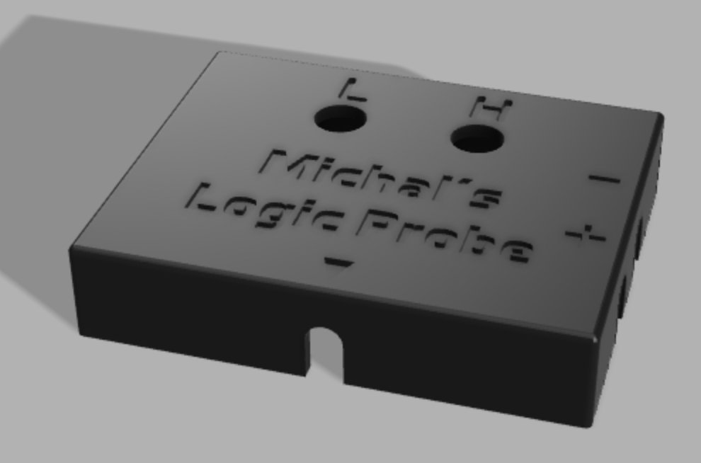
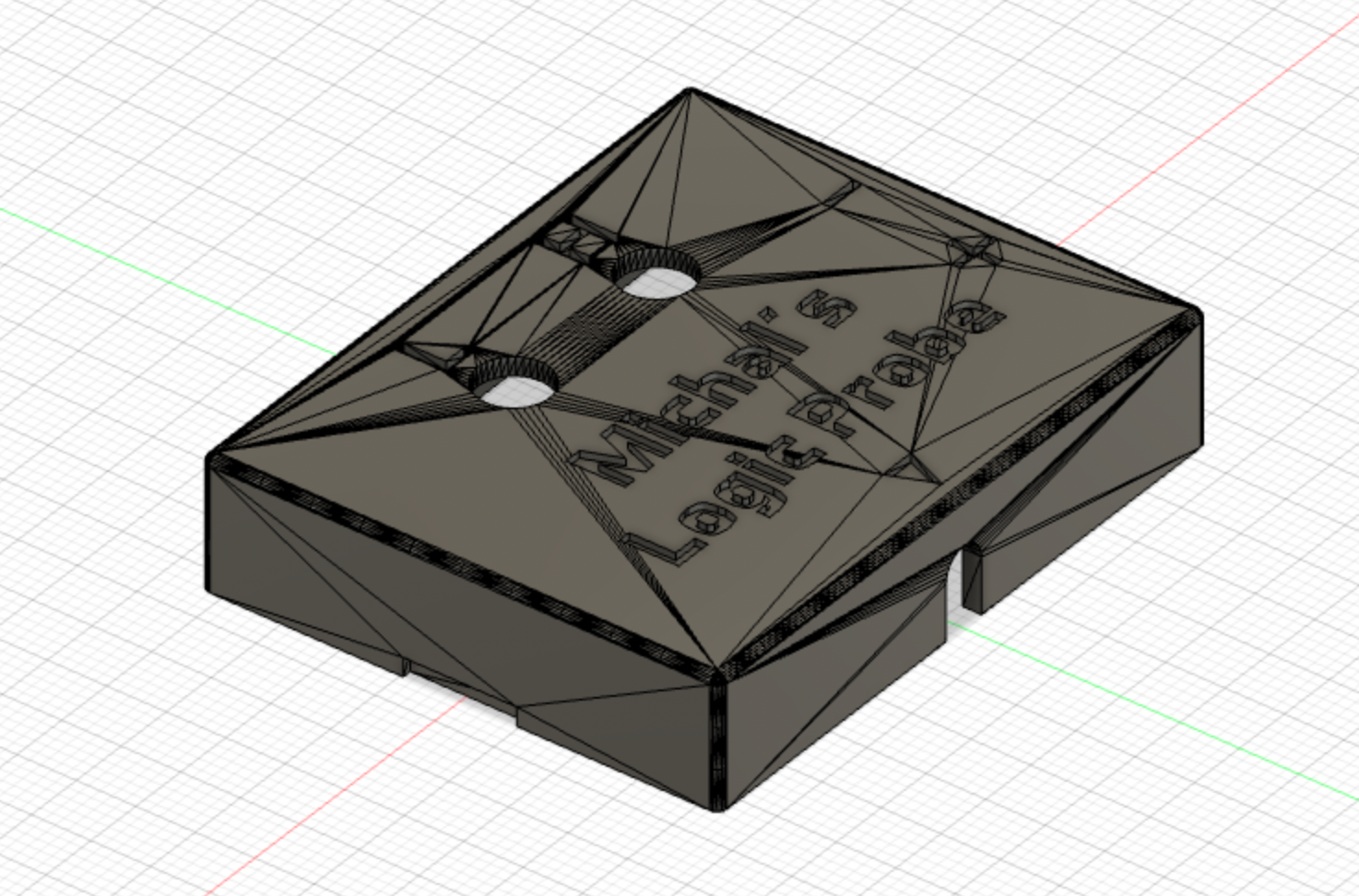
Alright- It’s now time to finish this! First off, I 3D printed the enclosure for the probe. Now I could have just used a provided .stl file — but that’s boring. I customised it with my name instead in Fusion 360. This was relatively painless- but Fusion 360 probably isn’t the best for editing .stls. The final geometry is a good example of why. It would have been nice to have access to the original Fusion 360 files, but it turned out fine enough in any case.
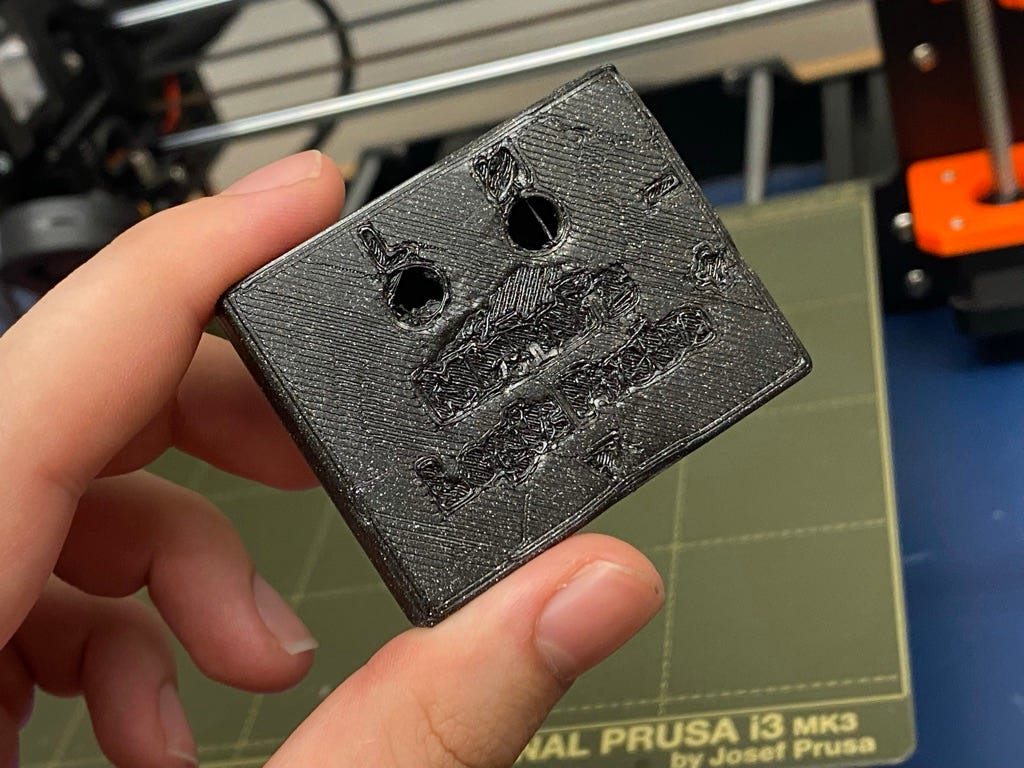


After slicing the .stl in Cura, printing itself proved a challenge, as the first print totally butchered the custom top. Turns out I made the bed too hot and the nozzle temp too low for this amazing shiny black filament. Luckily the other two parts printed well enough, and so with some adjusted settings I was able to reprint the top (mostly) successfully. Unfortunately, the Prusa i3 was set up to be a bit too hasty and still butchered the “H”, but in the name of conserving filament I called it okay enough.



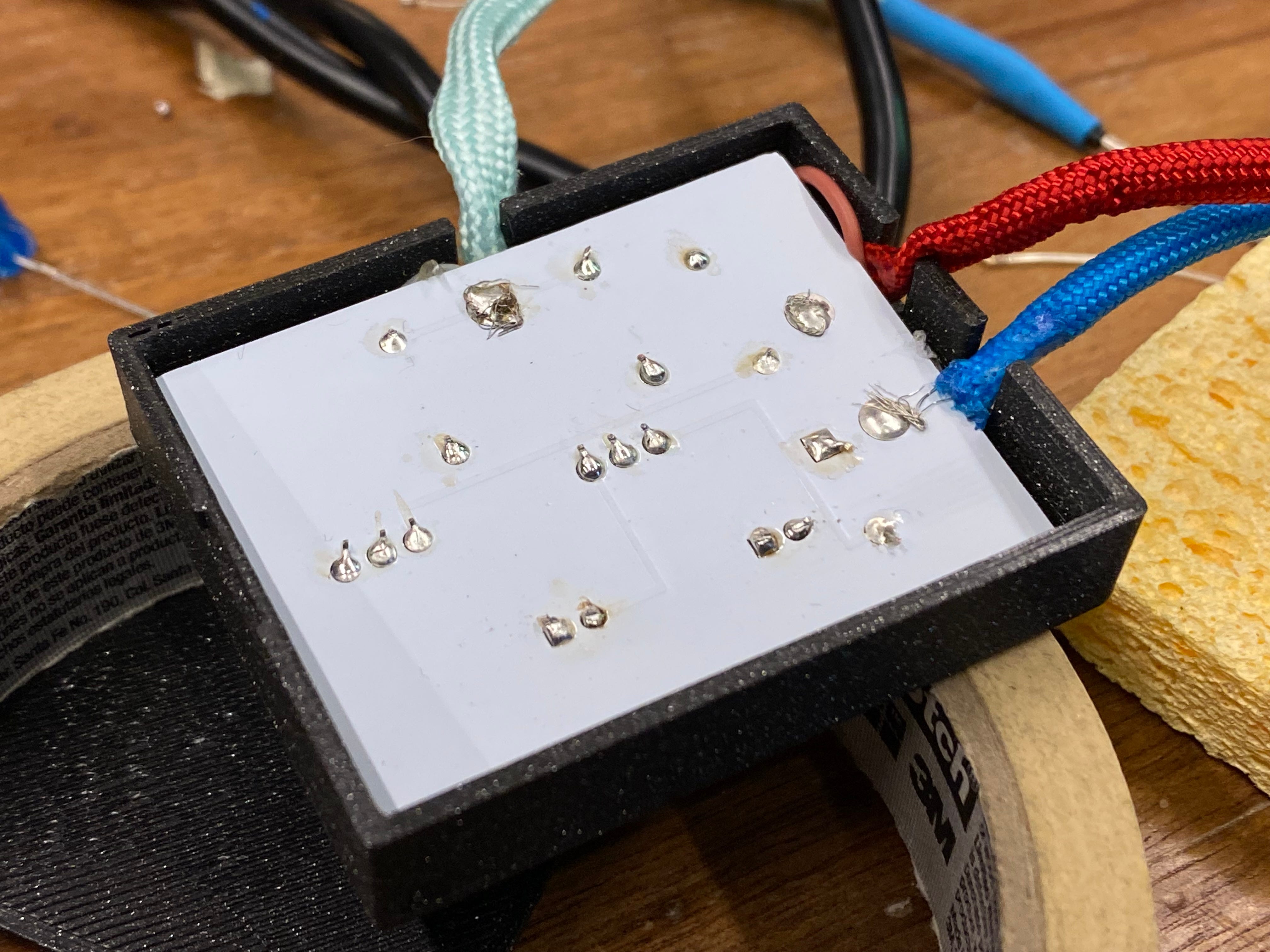
Finally, it was time to assemble and do final soldering. I started by soldering the wires made earlier to the board. I cut off the excess wire, stripped about an inch, and looped it through the PCB before soldering it in place. As recommended by our class guide, I then used a generous amount of hot glue to strengthen the hold and to prevent the wire from snapping off. Unfortunately I was a bit too liberal and had to reglue it with a bit less.

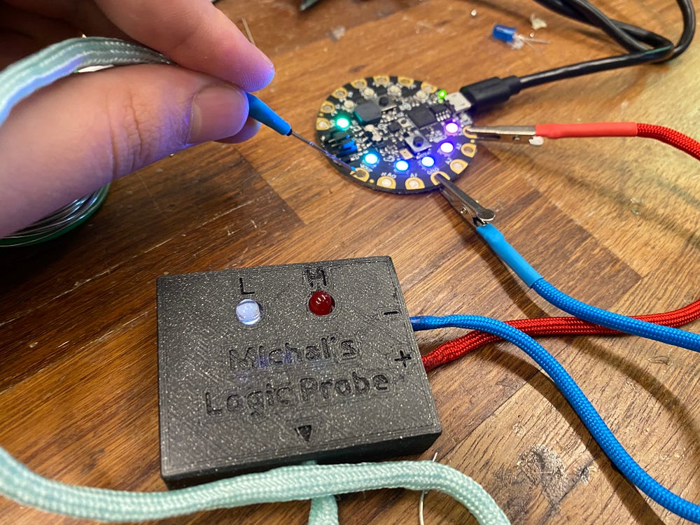
For the final step, I fit in the PCB with LEDs. After making sure the alignment was good, I folded the LEDs pins in place and soldered them to the board. As you might notice, I chose to use a white LED instead of a blue one. They both have similar voltage drops/current draw, so it shouldn’t be a problem overall. I think it adds a bit of uniqueness in addition to the custom housing. Plus it looks cool! After soldering the LEDs in place, I used a wire cutter to cut off the excess pins and finish off the Logic Probe.
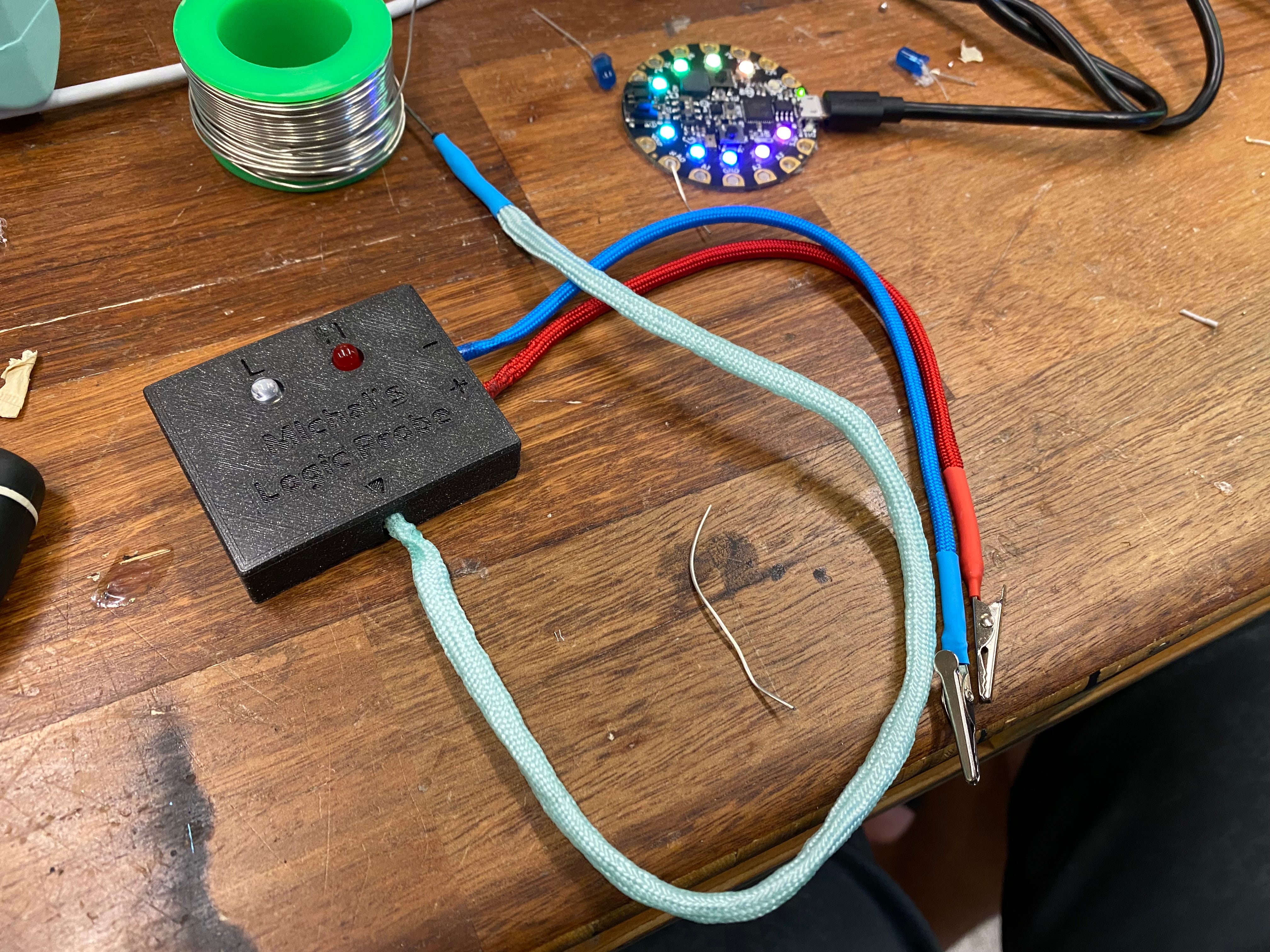

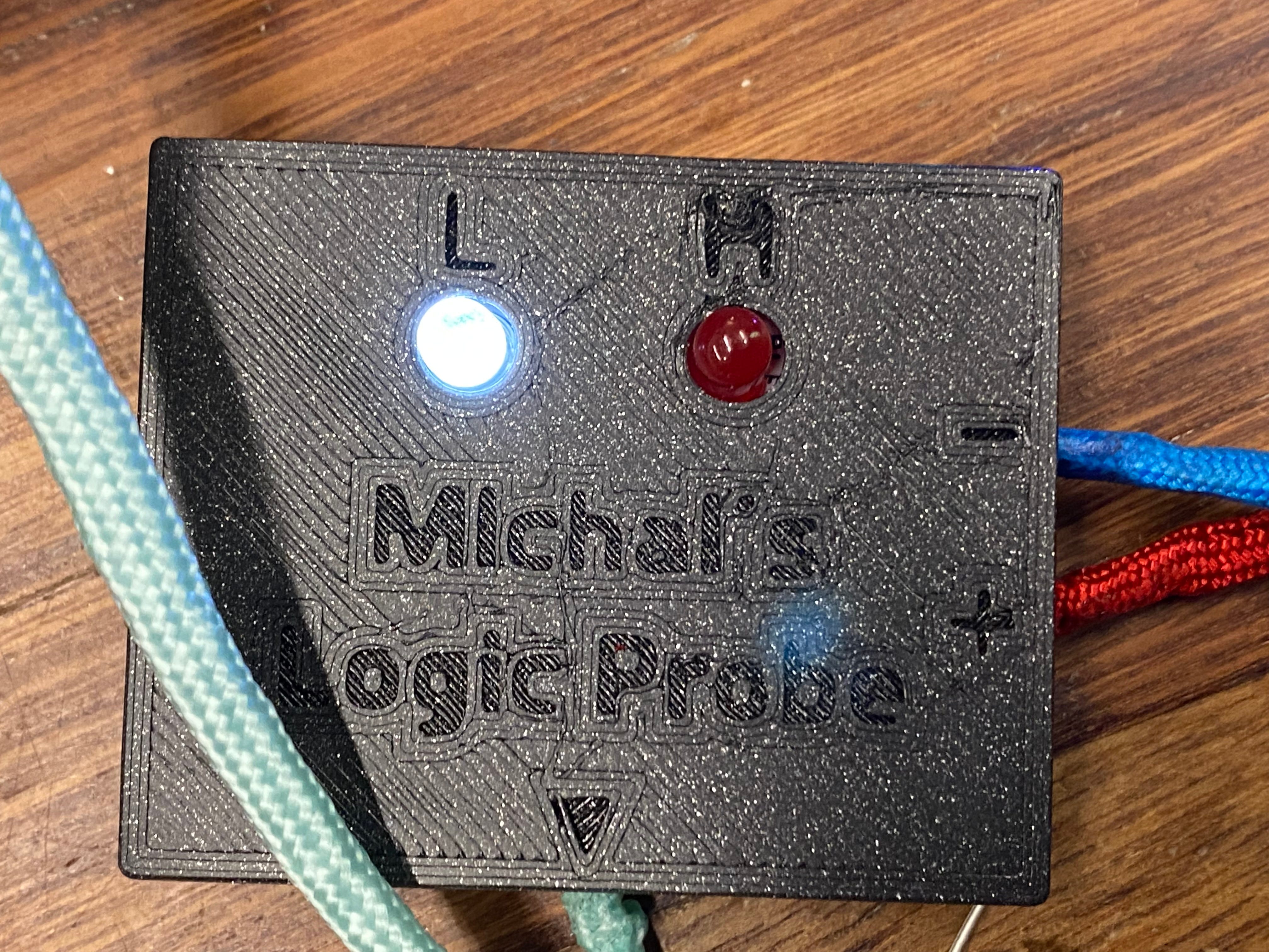


And that’s that! As you can see, the probe works flawlessly in testing, showing Low when touched to ground and High when touched to a 3.3v source. The build quality turned out pretty good despite the print and some problems trying to finesse the excess wiring for flush enclosure fit. The mint paracord also feels a bit…loose? I’m not sure why but it definitely doesn’t feel as good as the blue and red paracord. Still, I like the look.
In the end I had a lot of fun refreshing my soldering skills, as well as 3D printing and CAD’ing for the first time! This is a great project that not only is simple enough for beginners, but is also a very useful tool! I highly recommend trying it out for yourself.


